|


Press
the "Forward" button to continue.
Planning
a Fiber System |
7.
What is the total expected loss for the link between
A and C? 850nm _________ dB 1300nm __________
dB |
Link
Loss Calculation Steps
1. Figure length of fiber link
2. Convert to meters
3. Add up connectors, divide by two
4. Figure expected loss by adding length loss
to connector loss |
| We
add the expected connector loss (3.75 dB) to arrive
at the total expected loss at 850 nm. 1.30 dB plus
3.75 dB equals 5.05 dB. By adding the length loss
at 1300nm, .558dB, to the expected connector loss,
3.75dB, we find that the total expected loss at
1300nm is 4.308dB. Notice that there is less expected
loss at 1300 nm than at 850 nm. Also note that the
expected losses from the connector sets remains
the same value, regardless of the wavelength being
calculated. The “optical budget” of the proposed
fiber connection using the two links has been determined.
The installation company can now consider what optoelectronic
device set will deliver the signals needed, and
be able to operate within the expected loss values. |
 |
Remember
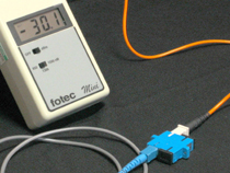
that these are just calculations, not field tests.
It is very important to field test the link(s) with
an optical loss meter set to determine that the
links are within industry standards. Excessive bending,
poor installation, or poor connectors may cause
the fiber link to be unusable without repair or
modifications. |
|
|
| LESSON
REVIEW |
Key
Points:
1.
Added the expected length loss to the expected losses from
connector pairs and splices provides an optical budget estimate
for a fiber link.
2. Links should be tested with an optical loss meter set to
verify link calculations.
3. If the loss meter test indicates higher than expected loss,
there is either problems with the installation or the original
calculation is incorrect.
|
Pop
Quiz:
True
or False
Multimode fiber links will have more loss at 1300nm than at
850nm.

|
|
|
|
|
| |
|
|
|
|
 |
|
|
|
|
|
|
|


